- English
- French
- German
- Portuguese
- Spanish
- Russian
- Japanese
- Korean
- Arabic
- Greek
- German
- Turkish
- Italian
- Danish
- Romanian
- Indonesian
- Czech
- Afrikaans
- Swedish
- Polish
- Basque
- Catalan
- Esperanto
- Hindi
- Lao
- Albanian
- Amharic
- Armenian
- Azerbaijani
- Belarusian
- Bengali
- Bosnian
- Bulgarian
- Cebuano
- Chichewa
- Corsican
- Croatian
- Dutch
- Estonian
- Filipino
- Finnish
- Frisian
- Galician
- Georgian
- Gujarati
- Haitian
- Hausa
- Hawaiian
- Hebrew
- Hmong
- Hungarian
- Icelandic
- Igbo
- Javanese
- Kannada
- Kazakh
- Khmer
- Kurdish
- Kyrgyz
- Latin
- Latvian
- Lithuanian
- Luxembou..
- Macedonian
- Malagasy
- Malay
- Malayalam
- Maltese
- Maori
- Marathi
- Mongolian
- Burmese
- Nepali
- Norwegian
- Pashto
- Persian
- Punjabi
- Serbian
- Sesotho
- Sinhala
- Slovak
- Slovenian
- Somali
- Samoan
- Scots Gaelic
- Shona
- Sindhi
- Sundanese
- Swahili
- Tajik
- Tamil
- Telugu
- Thai
- Ukrainian
- Urdu
- Uzbek
- Vietnamese
- Welsh
- Xhosa
- Yiddish
- Yoruba
- Zulu
Design tips for gear parts made by low pressure casting
Gear components manufactured through low pressure casting require careful consideration during the design phase to achieve optimal mechanical properties and dimensional accuracy. The production of complex geometries like fire pump impellers and transmission components has made this manufacturing process—which requires filling molds under controlled pressure conditions—especially pertinent. The A356 aluminum alloy, commonly specified for such applications, offers an excellent balance of strength and castability when processed correctly. Design engineers working with low pressure casting gear parts must address several geometric considerations to ensure successful production outcomes while maintaining the structural integrity required for demanding operational environments.

Smooth and Rounded Corners
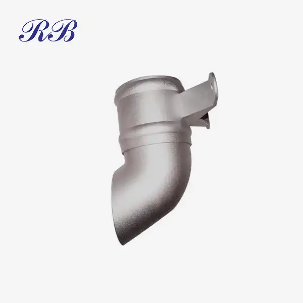
Sharp internal corners in low pressure casting gear parts create significant manufacturing challenges and compromise structural performance. When molten metal flows through the cavity during the casting cycle, sharp transitions cause turbulence that may introduce porosity or incomplete filling. These defects concentrate stresses during service loading, potentially initiating crack propagation at precisely the locations where gear teeth engage under cyclic loading conditions.
A number of issues are addressed at once by the use of radiused transitions. From a fluid dynamics perspective, rounded corners facilitate laminar flow patterns as the aluminum alloy fills the mold cavity. This becomes especially important when casting features where hydraulic performance is determined by uniform metal distribution, like the intricate blade geometries found in fire pump impellers. A minimum fillet radius of 3mm has been documented in foundry practice for components in the 2kg weight range, though specific applications may warrant larger radii depending on wall thickness ratios and anticipated stress concentrations.
Beyond manufacturing considerations, rounded corners fundamentally alter the stress distribution within gear components. Finite element analysis consistently demonstrates that generous radii distribute loads across larger surface areas, reducing peak stresses by factors ranging from two to four compared to sharp corner geometries. This becomes especially important for components subjected to cyclic loading, where fatigue life correlates directly with stress concentration factors. Engineers at facilities producing low pressure casting gear parts through CNC machining and shot blasting surface treatments have observed that components with properly radiused corners exhibit extended service intervals even under abrasive slurry conditions common in fire protection systems.
The transition zones between the hub components and gear teeth are another location where corner geometry is important. Abrupt changes in cross-section create notch effects that reduce fatigue strength regardless of material properties. Implementing smooth blending in these regions, while potentially increasing pattern complexity, yields components better suited for applications involving shock loads or vibration. Production data from facilities maintaining ISO9001:2015 certification indicates that rejection rates due to structural failures decrease measurably when design specifications mandate minimum corner radii throughout the component geometry.

Proper Draft Angle
Pattern removal from sand molds or permanent tooling requires adequate draft angle to prevent surface damage during the demolding sequence. Unlike high pressure die casting where ejection systems actively push components from tooling, low pressure casting relies primarily on gravity and controlled pressure release for part extraction. Insufficient draft creates friction between the solidified casting and mold surfaces, resulting in torn surfaces or dimensional distortion that subsequent machining operations cannot fully correct.
Draft angle requirements vary based on several interdependent factors. Casting depth significantly influences the necessary angle, as taller features experience greater surface contact area during withdrawal. For low pressure casting gear parts with hub heights exceeding 50mm, draft angles typically range from 1.5 to 3 degrees, though specific tooling designs and alloy characteristics may alter these baseline values. Surface texture also impacts draft requirements; rougher mold surfaces demand steeper angles to overcome mechanical interlocking between the casting surface and cavity walls. Components destined for shot blasting surface treatment can tolerate slightly more aggressive draft angles since the subsequent peening process removes minor surface imperfections.
The economic implications of proper draft angle specification extend beyond immediate manufacturing costs. Castings produced with inadequate draft frequently require additional grinding or machining to achieve specified tolerances, increasing production time and material waste. This is especially important for customized gear combinations when strict dimensional control is required per OEM requirements. Production facilities in Xi'an, China producing fire pump impellers at capacities reaching 5000 pieces have documented that optimal draft angles reduce secondary operations by approximately 20 percent while improving dimensional consistency across production runs.
Internal features such as cooling passages or lightening pockets present unique draft angle challenges. These features often require cores that must be extracted through narrow openings, demanding careful attention to removal sequences during tooling design. Collapsible cores or side pulls may become necessary when geometric constraints prevent adequate draft on internal surfaces. Design engineers must balance the functional requirements of gear tooth profiles against manufacturing constraints, occasionally accepting minor deviations from ideal involute geometries to accommodate practical tooling limitations.

Controlled Wall Thickness and Ribbing
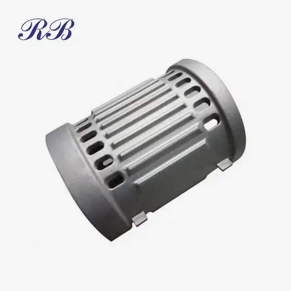
Uniform wall thickness throughout low pressure casting gear parts promotes consistent solidification rates and reduces internal stresses that develop during cooling. Sections that solidify at different rates experience thermal gradients that induce residual stresses, potentially warping finished components beyond acceptable tolerances. Gear parts with abrupt thickness transitions frequently develop shrinkage porosity in heavier sections, as these regions remain molten while surrounding material has already solidified, creating feeding path restrictions.
The challenge lies in reconciling structural requirements with casting constraints. Gear hubs require sufficient thickness to transmit torque without yielding, yet excessive material in these regions promotes the very defects designers seek to avoid. Target wall thickness ratios typically range from 1:1.5 to 1:2 between thin and thick sections, though specific geometries may permit wider ranges when solidification simulation validates acceptable outcomes. Components manufactured from A356 aluminum alloy benefit from this material's relatively narrow solidification range, which reduces hot tearing susceptibility compared to alloys with wider freezing intervals.
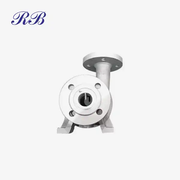
Strategic rib placement addresses the conflicting demands of strength and castability. Ribs increase section modulus without proportionally adding weight, distributing loads while maintaining relatively uniform wall thickness throughout the structure. For low pressure casting gear parts intended for fire pump applications, radial ribs connecting outer rim sections to central hubs provide torsional rigidity while creating flow channels that assist mold filling. Rib thickness generally follows the rule of measuring 50 to 70 percent of the nominal wall thickness, preventing the ribs themselves from becoming problem areas during solidification.
Spacing between ribs influences both structural performance and manufacturing success. Ribs placed too closely create narrow channels that resist metal flow, potentially trapping gas or promoting oxide formation as the turbulent stream folds back on itself. Conversely, excessive spacing reduces structural efficiency, requiring either heavier wall sections or acceptance of reduced stiffness. Finite element modeling combined with flow simulation software allows engineers to optimize rib configurations before committing to tooling fabrication, reducing development iterations and accelerating time to production.
The cooling rate variations inherent in ribbed structures necessitate attention to fillet radii at rib intersections. These junctions represent potential hot spots where three material sections converge, creating the last areas to solidify within the casting. Generous radii at rib roots facilitate heat extraction while reducing stress concentrations, though designers must verify that increased material volume in these regions does not create new feeding challenges. Production experience with low pressure casting gear partsundergoing CNC machining after casting indicates that properly designed rib structures actually improve machinability by providing consistent workpiece rigidity during cutting operations.
Contact Information
Rongbao Enterprise specializes in manufacturing precision cast components including low pressure casting gear parts for fire pump impellers and related applications. Our facility in Xi'an, China maintains ISO9001:2015, ISO14001, and ISO45001 certifications, ensuring quality management throughout production processes. For technical inquiries regarding custom casting specifications or to discuss your component requirements, contact our engineering team at steve.zhou@263.net or zhouyi@rongbaocasting.com.
Manufacturing low pressure casting gear parts through low pressure casting demands integrated consideration of geometric features that influence both production feasibility and component performance. The three design elements discussed—corner radii, draft angles, and wall thickness control—interact throughout the manufacturing sequence from mold filling through final machining operations. Engineers who comprehend these connections create parts that satisfy functional specifications while yet being profitable to produce in large quantities. Iterative prototyping is less necessary when casting behavior is predicted throughout the design phase, which expedites development timeframes for specialized applications where dependability is essential, such as fire prevention equipment. This is made feasible by the advancement of manufacturing technology and the sophistication of simulation tools.
References
- Campbell, J. (2015). Complete Casting Handbook: Metal Casting Processes, Metallurgy, Techniques and Design. Butterworth-Heinemann, Oxford, United Kingdom.
- Bonollo, F., Urban, J., Bonatto, B., & Botter, M. (2005). Gravity and low pressure die casting of aluminium alloys: a technical and economical benchmark. La Metallurgia Italiana, 97(6), 23-32.
- Kaufman, J. G., & Rooy, E. L. (2004). Aluminum Alloy Castings: Properties, Processes, and Applications. ASM International, Materials Park, Ohio.
- Gebelin, J. C., Jolly, M. R., Cendrowicz, A. M., Cirre, J., & Blackburn, S. (2004). Modelling of the pressure die casting process applied to the production of turbocharger compressor wheels. Journal of Materials Processing Technology, 152(2), 188-198.
- Dispinar, D., & Campbell, J. (2011). Effect of casting conditions on aluminium metal quality. Journal of Materials Processing Technology, 211(2), 213-220.

Learn about our latest products and discounts through SMS or email